Frequency of incorrect limb electrode placement.9

Javier García-Niebla1
doi: http://dx.doi.org/10.5195/ijms.2014.93
Volume 2, Number 3: 87-89
For correct electrocardiography (ECG) diagnosis and interpretation, it is important not only to distinguish normal from pathological electrocardiograms, but also to ensure that they have been properly recorded.
Heden et al.,1 reported that 2% of the 11,000 ECGs analyzed showed interchanged electrode placement. Thus, if 300 million ECGs are performed annually in the world, 6 million are erroneously recorded. This figure could even triple if one includes other frequent mistakes, such as vertical displacement of precordial electrodes and the distal placement of these on the limbs instead of the trunk.2 Few manuals on electrocardiography have devoted space to warn about the effects of ECG recordings that do not conform to standards, but it seems that this is changing.3
This issue of the Journal contains two interesting articles by Rosen et al., who form part of the research group led by Dr. Adrian Baranchuk, which address the most common mistakes made in daily practice in relation to improper placement of limb and precordial electrodes, as well as tell-tale signs for their detection.4, 5
In this editorial we will elaborate on certain issues directly related to possible errors on performing an ECG.
Yes. Patients must be informed of the procedure to be performed, emphasizing that it is painless and harmless but they must lie still, breathe normally and refrain from talking. Nervousness and sweating are to be resolved before starting the procedure. Proper skin preparation, with shaving if necessary, is required to reduce impedance and ensure adhesion of the electrode. This greatly helps to minimize the appearance of artifacts that can sometimes cause significant diagnostic errors.6
Yes. They are generally easy to identify. Only one pattern, resulting from the reversal of left arm and left leg electrodes, may be easily overlooked, even by experts. The presence of a P wave in lead I with greater amplitude than that in lead II and a positive terminal P wave morphology (-/+) in lead III can sometimes alert us to this error.7 Given the low specificity of these criteria, it is advisable to check for this error and repeat the ECG to ensure correct electrode placement.
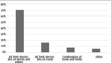
No. Proximal placement of limb electrodes or their placement on the trunk is not compatible with a standard ECG.8 The advent of easily applicable adhesive electrodes with decreased muscle noise has favored this practice (Figure 1).9 ECG changes are clearly visible when limb electrodes are placed on the trunk. In these cases, there is a QRS axis deviation to the right, which decreases the voltage of the R wave in leads I and aVL and increases it in leads II, III, and aVF. In a patient with necrotic Q wave in leads II, III and aVF, placing limb electrodes on the trunk may reduce both the voltage and the duration of the wave. If for any reason we need to perform the ECG with this non-standard placement (a patient with Parkinson's, for example), this should be expressly recorded in writing and taken into account in the interpretation.
Figure 1.Frequency of incorrect limb electrode placement.9

Yes, precordial lead electrodes must be placed exactly on their specific internationally established anatomical locations.10 Se veral published studies have described the ECG changes that occur when the electrodes are misplaced.11, 12
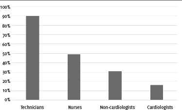
No. Even technicians with an average of 15 years or more experience and who perform over 30 ECGs a day can make important mistakes.11 However, their theoretical knowledge about precordial lead placement is superior to that of other professionals (Figure 2).13 The most common mistakes include:
Proportion of professionals who correctly positioned the V1 electrode (adapted from Rajaganeshan et al.).14

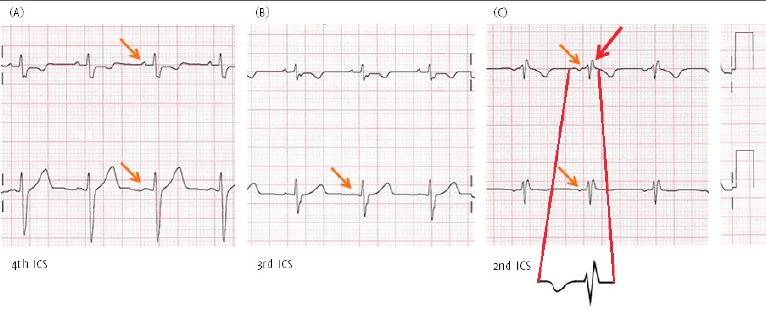
Three morphologies help identify high placement of these electrodes (Figure 3)14, 15:
The P wave is positive in V1-V2 (arrows) when the electrodes are correctly placed (A) on the 4th intercostal space (ICS). When V1-V2 electrodes are misplaced on the 3rd ICS (B), the low-voltage or flattened P wave in V2 (arrow) is the tell-tale sign of high placement. And when the V1-V2 electrodes are misplaced on the 2nd ICS, one sees a negative P wave and rsR’ (red arrow) which indicate high placement of the electrodes (C).

High positioning of the electrodes V1-V2 can mimic a Brugada type 2 pattern. However the r' in this case is narrow with the base of the lower triangle measuring less than 4 mm.16, 17
Yes. When filters are applied to prevent unwanted noise and obtain better quality recording of the cardiac signal, the ECG can sometimes be markedly affected unless the recommended cutoffs are applied:
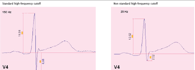
If the cutoff is too low, signals which are important from the clinical point of view can be eliminated (pacemaker spikes, amplitude of the R wave, QRS notches, etc.) (Figure 4).18 The cutoff frequency should be at least 150 Hz in the case of adults and adolescents and up to 250 Hz in the case of children.
Figure 4.Effect of a high-pass filter in lead V4. Note how the voltages of the R wave (14.84 mm to 12.82 mm) and the S wave (6.68 mm to 2.52 mm) are reduced when applying a non-standard 25Hz filter.

It is important to remove the noise generated by a wandering baseline which may occur as a result of small movements and breathing of the patient. Inadequate filter application can result in significant distortion of the ST segment and T wave, simulating acute coronary syndrome or Brugada syndrome.19 The recommended cutoff is 0.05 Hz, increasing up to 0.67 Hz if linear filters with zero phase distortion are used.
In view of the above considerations, it is necessary to promote specific training programs and refresher courses on the performance and interpretation of ECGs, based on the latest recommendations made by the major international scientific societies. These should include the correct placement of the electrodes, assimilating the significance of correct technique, the reading of normal and pathological patterns, together with a specific focus on recognizing ECG patterns resulting from improper positioning of electrodes, the identification of artifacts and other technical problems that could lead to misinterpretation.
None.
The Author has no funding, financial relationships or conflicts of interest to disclose.
1. Heden B, Ohlsson M, Edenbrandt L, Rittner R, Pahlm O, Peterson C. Artificial neural networks for recognition of electrocardiographic lead reversal. Am J Cardiol. 1995 May 1;75(14):929–33.
2. García-Niebla J, Llontop-GarcíaP, Valle-Racero JI, Serra-Autonell G, Batchvarov VN, de Luna AB. Technical mistakes during the acquisition of the electrocardiogram. Ann Noninvasive Electrocardiol. 2009 Oct;14(4):389–403.
3. Bayés de Luna A. Clinical electrocardiography: a textbook. 4th ed. Chichester, West Sussex, UK: Wiley-Blackwell; c2012.
4. Rosen A, Koppikar S, Shaw C, Baranchuk A. Common ECG lead placement errors. Part I: Limb lead reversals. Int J Med Students. 2014 Jul-Oct;2(3):92–8.
5. Rosen A, Koppikar S, Shaw C, Baranchuk A. Common ECG lead placement errors. Part II: Precordial Misplacements. Int J Med Students. 2014 Jul-Oct;2(3):99–103.
6. Barake W, Baranchuk A, Pinter A. Pseudo-ventricular tachycardia mimicking malignant arrhythmia in a patient with rapid atrial fibrillation. Am J Crit Care. 2014 May;23(3):270–2.
7. Abdollah H, Milliken JA. Recognition of electrocardiographic left-arm/left-leg lead-reversal. Am J Cardiol. 1997 Nov 1;80(9):1247–9.
8. Pahlm O, Haisty WK Jr, Edenbrandt L, Wagner NB, Sevilla DC, Selvester RH, Evaluation of changes in standard electrocardiographic QRS waveforms recorded from activity-compatible proximal limb lead positions. Am J Cardiol. 1992 Jan 15;69(3):253–7.
9. Turner AM 12 Lead recordings: Implications of an inconsistent approach. Cardiology News 2006; 9: 10–12.
10. Kligfield P, Gettes LS, Bailey JJ, Childers R, Deal BJ, Hancock EW, Recommendations for the standardization and interpretation of the electrocardiogram: part I: The electrocardiogram and its technology: a scientific statement from the American Heart Association Electrocardiography and Arrhythmias Committee, Council on Clinical Cardiology; the American College of Cardiology Foundation; and the Heart Rhythm Society: endorsed by the International Society for Computerized Electrocardiology. Circulation. 2007 Mar 13;115(10):1306–24.
11. Garcia-Niebla J. Comparison of p-wave patterns derived from correct and incorrect placement of V1-V2 electrodes. J Cardiovasc Nurs. 2009 Mar-Apr;24(2):156–61.
12. Zema MJ, Kligfield P. ECG poor R-wave progression: review and synthesis. Arch Intern Med. 1982 Jun;142(6):1145–8.
13. Wenger W, Kligfield P. Variability of precordial electrode placement during routine electrocardiography. J Electrocardiol. 1996 Jul;29(3):179–84.
14. Rajaganeshan R, Ludlam CL, Francis DP, Parasramka SV, Sutton R. Accuracy in ECG lead placement among technicians, nurses, general physicians and cardiologists. Int J Clin Pract. 2008 Jan;62(1):65–70.
15. Garcia-Niebla J, Rodriguez-Morales M, Valle-Racero JI, de Luna AB. Negative P wave in V1 is the key to identifying high placement of V1-V2 electrodes in nonpathological subjects. Am J Med. 2012 Sep;125(9):e9–10.
16. García-Niebla J, Baranchuk A, de Luna AB. True Brugada pattern or only high V1-V2 electrode placement? J Electrocardiol. 2014 Sep-Oct;47(5):756–8.
17. Baranchuk A, Enriquez A, García-Niebla J, Bayés-Genís A, Villuendas R, Bayés de Luna A. Differential diagnosis of rSr’ pattern in leads V1-V2. Comprehensive review and proposed algorithm. Ann Noninv Electrocardiol. 2014: Forthcoming.
18. Garcia-Niebla J, Serra-Autonell G. Effects of inadequate low-pass filter application. J Electrocardiol. 2009 Jul-Aug;42(4):303–4.
19. Garcia-Niebla J, Serra-Autonell G, Bayes de Luna A. Brugada syndrome electrocardiographic pattern as a result of improper application of a high pass filter. Am J Cardiol. 2012 Jul 15;110(2):318–20.
Javier García-Niebla, 1 Servicios Sanitarios del Área de Salud de El Hierro, Valle del Golfo Health Center. Ex-member of the Board of Directors, Spanish Association of Nursing in Cardiology. Collaborating lecturer of the University School of Nursing. University Hospital La. Candelaria, Spain.
About the Author: Javier García Niebla is a registered nurse with a degree in Nursing from the University of La Laguna and an associate lecturer at the University School of Nursing, Hospital “Ntra. Sra. de La Candelaria”. For almost six years he directed the webpage of the Spanish Association of Nursing in Cardiology. As an investigator and author, he has published in dozens of scientific journals in the field of cardiology and is a recognized expert in electrocardiography, and a regular collaborator of Prof. Antoni Bayés de Luna.
Correspondence: Javier García-Niebla, Address: C/Marcos Luis Barrera 1, 38911 Frontera-El Hierro, Canaries, Spain. Email: jniebla72@hotmail.com
Cite as: García-Niebla J. The Quest for Quality Electrocardiographic Recording. Int J Med Students. 2014 Jul-Oct;2(3):87-9.
Copyright © 2014 Javier García-Niebla
International Journal of Medical Students, VOLUME 2, NUMBER 3, October 2014